All industrial fans work basically the same principle of action, and it no different with centrifugal fan design. The fluid strikes the moving (rotating) impeller and the impeller transfers it’s kinetic and dynamic energy to the fluid. As a result of this action, the fluid moves in a certain distance with greater pressure.
Centrifugal fans work on the centrifugation action. When fluid (usually air) strikes the impeller of the fan, the impeller transfers its rotational energy to the fluid by centrifugal force. Thus, the rotational energy of the impeller is transferred to fluid in form of radial energy under the action of centrifugal force.
Design options for Centrifugal Fans
There are several design variables of centrifugal fan. Some of them include:
- Number of blades
- Blade shape
- Blade curvature
- Axial length of blades
- Radial depth of blades
- Impeller diameter
- Guiding vanes
- Fan width
- Impeller clearance and exposure
- Material of construction
There are important factors which need to be considered while designing the blade curvature for the centrifugal fans. These include the action of the impeller imparting its rotational energy to the air via radial tip, backward curve or forward curve.
Design variables for centrifugal fans include blade angles, absolute velocity of the fluid, tangential velocity of the fluid, radial velocity of the fluid, radial velocity of the blade, and the velocity of the fluid relative to blade. The radial velocity component of the fluid (air) is constant throughout the impeller, so the rate of change of momentum is directly proportional to the rate of change of tangential velocity. To ease the designing of the centrifugal fan, it is better to resolve the components of absolute velocity (V) into Va and Vr. Subscripts a and r depict the axial and radial components of velocity, i.e. both perpendicular to each other.
In the diagram, the subscripts 1 and 2 represent influent and effluent streams of fluid. The rotating fan impeller, when comes in contact with the fluid, develops momentum in the fluid. Therefore, we can conclude that force developed by the fan is equal to the rate of change of momentum. Assuming there is no loss in power, ideal power can rise mass, M, to some height, H. All of the kinetic energy is transferred to gravitation potential energy. This kinetic energy of the moving fluid is entirely recoverable in the form of potential energy equal to the height of column of fluid for unit weight. Following equation represents this phenomenon:
![]()
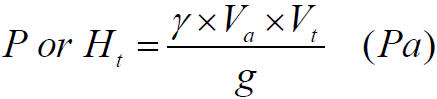
Pressure induced by the air of column of height H can be found by a well known equation i.e. P=ρ.g.h. Pressure can be found by finding the product of density, gravitational acceleration and height of fluid in column. So we can develop an equation for the pressure developed by the centrifugal fan:
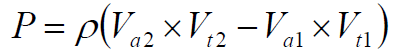
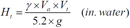
We can ignore the Va1 because air enters the centrifugal fan in the radial direction. So the equation of the total theoretical fan pressure and the pressure head can be represented by the equations:
We have a correlation to relate fan of speed, diameter of the impeller with the velocity. It is desirable, in practice, to relate theoretical pressure developed by the fan in terms of flow rates and geometry of the blades. This can be represented by the equating:
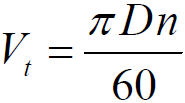
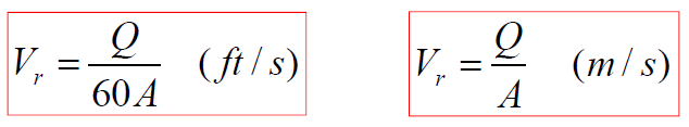
Here in this equation, n represents number of revolutions in (RPMs) and D represents the diameter of impeller. And finally we can find the radial velocity of centrifugal fan blade by the following correlation:
The important thing to take away is that your fan will be designed to move the air that you need moved, and will do so reliably and efficiently. If you have any questions regarding centrifugal fan design, be sure to give Custom Fans a call.